•Welds views
•Surface roughness
•Tolerance
•Edges of undefined shape
•Projection methods
•Measuring points
•Cross-sections
•Break lines
•Fasteners
•Holes
•and others.


An example of a drawing with various markings
CADprofi program has got typical markings that are used to create mechanical branch documentation. These markings are prepared in accordance with national and international standards, including PN, EN, ISO and DIN.
Markings are multivariant elements, which appearance and information can be in a quick and easy way customized. In this way, one multivariant symbol can replace many "traditional" symbols in the library, giving the user bigger possibilities to configure the type and appearance. Multivariant symbols can be freely modified with the Edit symbols command.
All marking are available in the Marks command. These symbols are also available in several additional commands, thanks to which user has got a quicker access to markings or symbols that he needs at the moment.
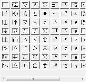
Commands used to mark technical drawings:
|
•Welds views •Surface roughness •Tolerance •Edges of undefined shape •Projection methods •Measuring points •Cross-sections •Break lines •Fasteners •Holes •and others.
|
An example of a drawing with various markings
|
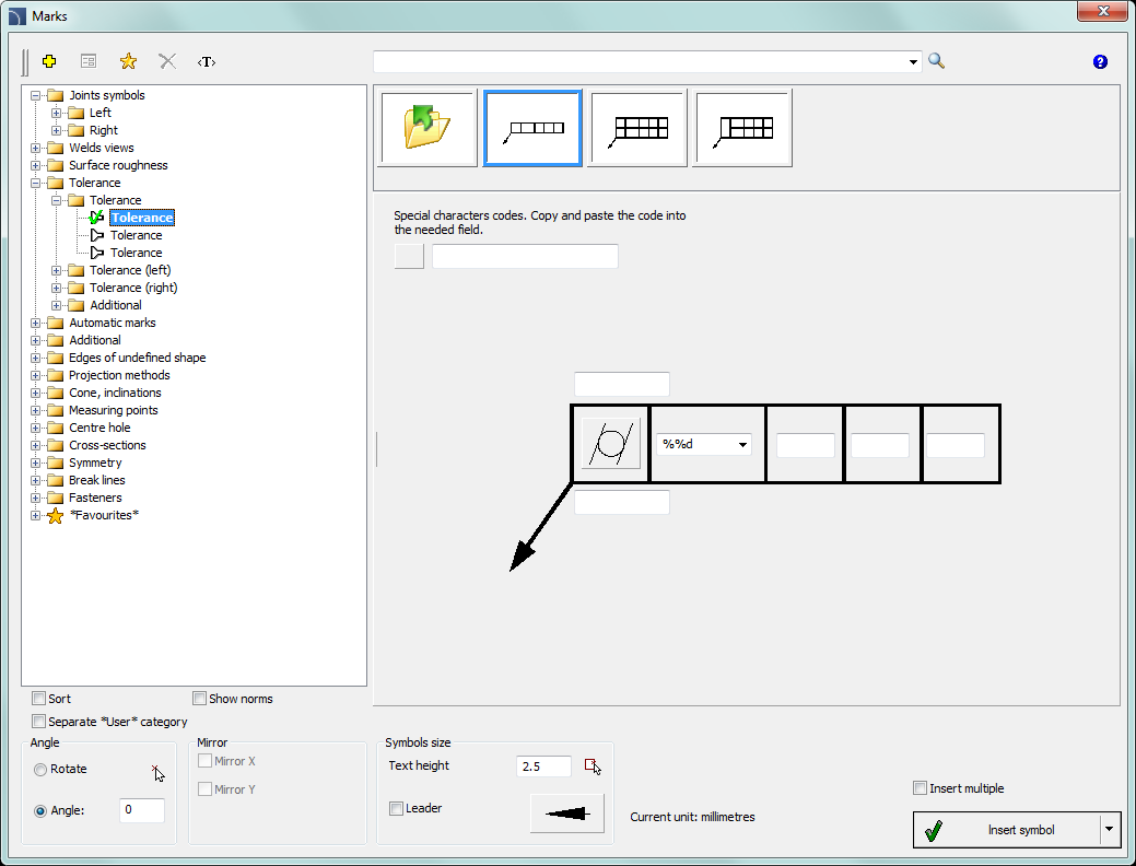
Marks dialog window
Marks dialog window contains the following items:
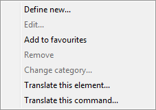
Tools menu:
•Define new  –
allows to add a new element to the database. Read more about it in the Defining user
blocks).
–
allows to add a new element to the database. Read more about it in the Defining user
blocks).
•Edit  – allows
to Editing user block
parameters).
– allows
to Editing user block
parameters).
•Add to favourites –
copies symbol to the *Favourites*).
–
copies symbol to the *Favourites*).
•Delete  –
deletes the selected symbols from the *Favourites*
category.
–
deletes the selected symbols from the *Favourites*
category.
|
Pop-up menu– options menu for the selected symbol, which is available after right clicking on the mouse button on the selected symbol. Commands in this menu are similar to the tools menu. |
|
Categories tree – a set of all categories and symbols in the library, shown as a pull-down tree. User can customize the display order by using the following options:
•Sort – alphabetical order of categories placement and their content.
•Show norms– enables/disables displaying symbols according to norms.
Thumbnail view – displays the content of currently selected category as thumbnails.
Angle/Rotation – possibility to specify a fixed angle when inserting an element or enabling the rotation option, in which element’s angle is defined by rotation during insertion.
Scale – specifies the size of inserted symbols. It is possible to enter the scale value or to indicate a symbol on the drawing whose scale user would like to use.
Mirror X, Y– enabling this option will create an X or Y mirror image for certain specified object.
Leader –
enables/disables usage of leader for descriptions. By clicking on the  button, that symbolizes the currently set
arrow type, user can change the following leader settings:
button, that symbolizes the currently set
arrow type, user can change the following leader settings:
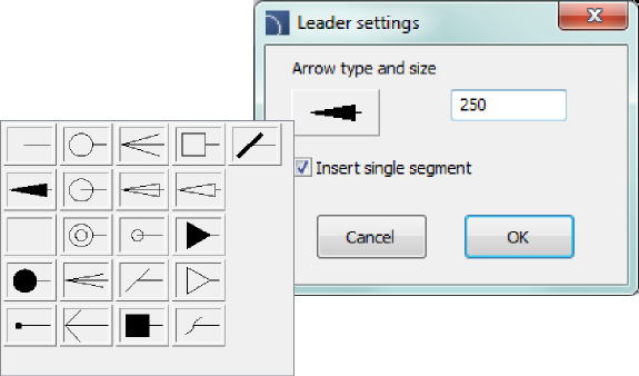
•Arrow type– symbol that is inserted in the leader starting point for example an arrow.
•Arrow size – determines the leader scale.
•Insert single segment –drawing of a one or multi-segment leader.
Insert multiple– enables/disables the possibility of inserting multiple symbols to the drawing. The insertion process requires from the user to press the Enter or Esc key when he finished inserting multiple symbols.
Text height – value that determines the text height and the whole block scale.
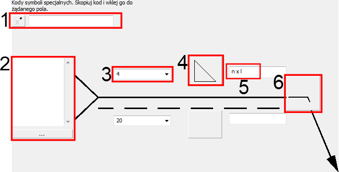
Symbol preview – an active area than contains the preview and parameters of selected marking. Each controls contained in this area give the possibility to customize the content of the multivariant symbol.
Examples of light control for multivariant symbols
1.
Special symbols codes field – gives the possibility
to display the code of the selected symbol so it can be copied and pasted
anywhere into a text field.
List of symbols is available after pressing the
 button.
2.
Text field – gives the possibility to enter any
multiline text. This field can be filled with any information selected from the
additional window that is opened with the Browse
 button.
3.
Pull-down list – gives the possibility to enter any
value or to select a value from the list (by pressing the  button). There are also lists available
that allow only to select the value (with the possibility to edit the
field).
button). There are also lists available
that allow only to select the value (with the possibility to edit the
field).
4. Graphical pull-down list – gives the possibility to select one of available graphical markings.
5. Editable field – gives the possibility to enter any text.
6. Supplementary symbol button – every time the user clicks on this button will display the next available symbol in the button field.
For some multivariant symbols, other controls may also be available, such as buttons used for measuring dimensions or angles in the drawing, enable/disable fields and more.
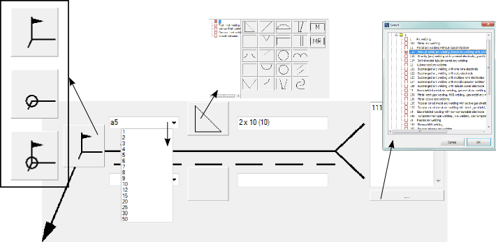
Procedures
1.
Run the Joint symbols  command.
2. In the dialog window select the needed symbol.
3.
Click the supplementary symbol button in order to get the Mounting weld  symbol.
4. Specify the weld thickness (e.g. a5) or select the value from the pull-down list.
5.
Click the icon of the weld symbol and from the newly opened dialog window select
the fillet weld symbol  .
.
6. Enter the weld length e.g. 2 x 10 (10).
7.
Click the browse  button and the
dialog window select the process of weld preparation e.g. 111 Manual metal arc welding.
button and the
dialog window select the process of weld preparation e.g. 111 Manual metal arc welding.
8. Enable the Leader option.
9. Click the OK button to insert the selected symbol into the drawing.
10. Specify the point that will be the leader beginning (P1).
11. Specify the symbol insertion point (P2) and possible rotation angle.
Settings in the dialog window
 |