An important part of each drawing is a frame and table.
The Frames and tables command offers users a convenient way to insert standard frames and tables to the drawing:
Tables - standard drawing tables.
Specifications - tables used to create drawing specifications.
Legends - standard legends that contain recommended line layers for installations.
User tables - empty tables, which can be defined by the user.
|
Hint Legends and drawing specifications can be created using the "Bill of materials". |

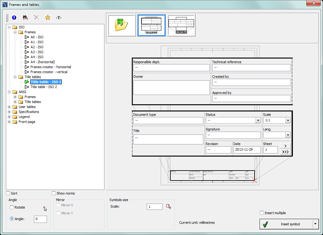
Frames and tables dialog window
The dialog window contains the following elements:
Angle/Rotate - gives the possibility to specify a fixed table insertion angle or to enable the rotation option, at which the angle is determined by the rotation.
Symbols size - a value that specifies the frame or table scale.
Frames

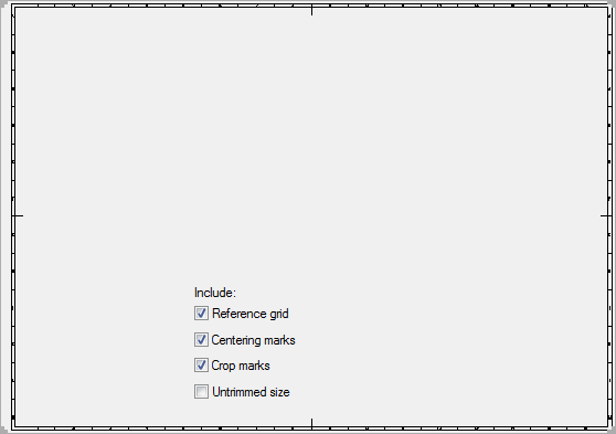
Frame view can be changed by turning on or off the following options: Reference grid, Centering marks, Crop marks and Untrimmed size.
Tables

All tables that are available in the program have got a possibility to edit the information about the project. Some tables are interactive, and for them it is possible to specify all data in the dialog window.
For interactive tables, edition or selection fields (with a
pull-down list of typical values under the  button) are available. If in one project
(drawing) user inserts many sheets, then the program can enumerate them with the
 and
and  button. The Data field is filled up automatically.
In order to edit tables after inserting them into the drawing, it's possible to use the CADprofi Attributes and descriptions command or an appropriate CAD program command e.g. Ddatte (_Ddatte).
6 Procedures
1.
Run the Frames and tables  command.
2. Select the frame, e.g. A2 - ISO.
3.
Select the elements that should be included in the frame
(Reference grid, Centering marks
etc.).
4. Click the Insert button to insert the frame into the drawing.
5. Once again run the Frames and tables command.
6. Select a table, e.g. Table - ISO 1.
7. Fill up the data about the project.
8. Click the OK button in order to insert the table into the drawing. As the insertion point user should indicate the right, down corner of the previously inserted table.
9. (Optional) Select the Edit symbols command to change the text in the tables or to change table into a different one.
10. (Optional) Change attributes in the table with the help of the CAD program. These changes can be done with the _Attedit command or in the object properties window.
User tables
User can create and add to the program his own tables or frames that are used in the drawing.
Tables that are included in CADprofi program allow user to edit data (blocks attributes). In order for the user tables to have the same functionality, it is necessary to include the appropriate attributes definitions for the created tables.
A convenient way to do this, is to insert and explode a standard table, edit it and afterwards add it as a user block.
The way how to define user own elements is described in detail in the Defining user blocks chapter.