The Lines - hydraulics and pneumatics command contains basic lines that are used in drawing of technological schemes, as well as, hydraulic and pneumatic schemes. It is possible to simultaneously draw many lines with a specified spacing and with a specified offset from objects that exist on the drawing. Program allows to define types of drawn lines, as well as to define user own system types.
In CADprofi program, schematical lines are mean as any pipes (pipe lines) or cables (electrical lines). Because of that all possibilities and options regarding the lines have been described in the CADprofi HVAC & Piping and CADprofi Electrical modules appropriate chapters.
This command also contains general and special lines, e.g. terrain identification, concrete flooring description, boundary lines and others.
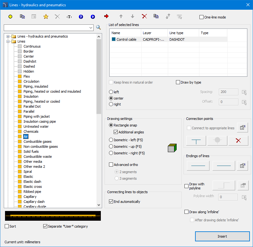
Lines - hydraulics and pneumatics dialog window
6 Procedures
1.
Run the Lines - hydraulics and pneumatics
 command.
2. In the dialog window select the desired line.
3.
Click the Add element to a list  button, or
double click on it to put it on the List of selected
lines.
button, or
double click on it to put it on the List of selected
lines.
4. (Optional) Repeat steps 2 and 3 in order to add more lines to the list.
5.
(Optional) Using the Copy selected rows  , Remove selected rows
 buttons add or remove the selected line from the list.
6.
(Optional) Using the Move selected rows down
 / Move selected rows up
  buttons change the order of the lines on the
list.
buttons change the order of the lines on the
list.
7. (Optional) Fill the details about line type, turn on/off the Draw by type option.
8. (Optional) If there is more than one line on the List of selected lines set the Offset value.
9. Specify the draw edge and the Spacing value if needed.
10. (Optional) If on the List of selected lines there is only one object you can set the connection and line endings options.
11. Enable/disable the End automatically option.
12. Click the OK button in order to start drawing a line by indicating points on the drawing. In order to finish click the Enter or Esc key.
Schematic lines are simple lines or polylines that's why it is also possible to draw lines with the CAD program standard commands such as Line or Polyline. However, it should be noted, that lines drawn in this way should be placed on appropriate layers. In order to match properties (e.g. layers), between the drawn objects, the Match properties command located in the CAD program can be used.
Hint:
To edit lines the „Schematic lines -edit” command is used.
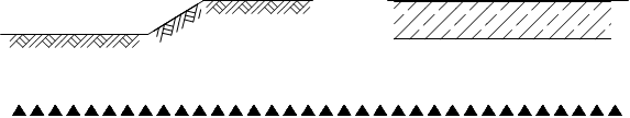
Example of different special lines with appropriate density scale (_Ltscale)

CP-Symbols