In CADprofi program schematic lines are drawn with lines or polylines that lie on the corresponding layers. The term "line kind" means the intended use of the selected line or a specific system (for example the L1,L2,L3 line). It is also possible to add "type" to the line, which defines its physical properties (e.g. YDY 3x2,5 for installation lines). Line type can be specified during drawing or later after the lines are already drawn with the Schematic lines - edit command.
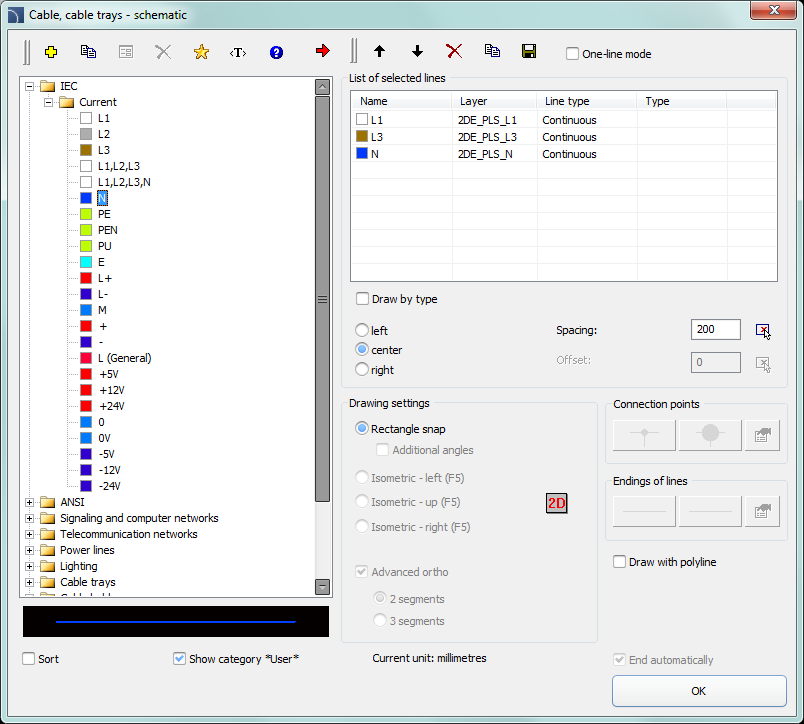
Standard line kinds from IEC and ANSI standards are grouped in categories. The Cable, cable trays - schematic command gives the possibility to draw one or many electrical installation lines. The process of drawing single lines is possible after selecting in the dialog window the necessary line kind and clicking the OK button. This procedure however doesn't allow to change the drawing settings. These options are available only after user has added a line to the list of list of selected lines. User can add many lines to this list, thanks to which it is possible to simultaneously draw several lines.
Cable, cable trays – schematic dialog window
The dialog window contains the following elements:
Lines menu – tools menu that allows user to manage lines’ kinds:
•Define new  –
allows to add a new position (line) to the list as a user line. Afterwards it
opens a new edit window and allows user to edit the
line data
–
allows to add a new position (line) to the list as a user line. Afterwards it
opens a new edit window and allows user to edit the
line data
•Copy  – copies
the selected line with all its parameters, therefore creating an element made by
user. Copied lines may be edited.
– copies
the selected line with all its parameters, therefore creating an element made by
user. Copied lines may be edited.
•Edit  – opens
the edit properties window of user created lines. Line name can be edited
directly by pressing the F2 key.
– opens
the edit properties window of user created lines. Line name can be edited
directly by pressing the F2 key.
•Delete  –
deletes the selected line from the list. Only the lines created by user may be
deleted.
–
deletes the selected line from the list. Only the lines created by user may be
deleted.
•Add to favourites  – adds the selected line to the *Favourites* list.
•Add element to a list  – adds the selected line to the List of selected lines.
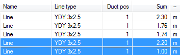
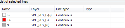
List of selected lines – contains lines, which will be drawn after clicking the OK button.
Menu of selected lines list – allows to manage the content of the selected lines list.
•Move selected rows down  – moves the selected line one position
down.
– moves the selected line one position
down.
Move selected rows up  – moves the selected line one position
up.
– moves the selected line one position
up.
•Remove selected rows – deletes the selected line from the
list.
•Copy selected rows – copies the selected line and adds it to
the list.
•Save as set of lines  – allows to save the current list of
selected lines as a new set.
– allows to save the current list of
selected lines as a new set.
|
Notice It's not possible to create (save) a set of lines if the list contains at least one line from the *Installations from drawing*. |
•One-line mode – this option blocks the possibility of adding more than one line to the List of selected lines. When enabled, program will convert the list of lines to a one line, chosen by user.
|
Type of line – it is possible to define Type for each line. |
|
In order to do this, user has to enter an appropriate value in the Type field that is located next to the line name on the List of selected lines.
Draw by type – enables the line type view for the newly created lines.
Lines conducting options – options that allow user to specify the way of drawing lines.
•Left – draws lines along the left edge.
•Center – draws lines symmetrically regarding the indicated points.
•Right – draws lines along the right edge.
•Spacing – the distance between the lines.
•Offset – an offset of the drawn lines from the points that are actually indicated in the drawing. This option allows to easily draw lines at a specified distance along the walls or other elements that exist in the drawing.

|
Hint Thanks to combining both the drawing edge and the offset user can lead the lines in accordance with any existing objects that are already inserted on the drawing e.g. walls. |

Show category *User*– enables/disables the visibility of the folder that contains all categories and lines created by user. If you turn off this feature then lines defined by user will be "mixed" with other standard CADprofi lines.
Drawing settings – line drawing options.
•Rectangle snap – 2D drawing default settings.
•Additional angles – enables the diagonal dimetric mode, through the use of polar tracking options (POLAR) according to the angle value that was defined in the CADprofi – options window.
•Isometric – allows to turn on the mode that allows to create isometric schemes (SNAPSTYLE variable). Three options are available (left, up, right) which can be easily switched during drawing isometry by pressing the F5 key.
Connection points – when drawing a single line it is possible to automatically insert connection points. There are several options available:
•Lack – no symbol on the line joint.
•Always – adding a symbol regardless of the kind of connected lines.
•On the same layer – adding a connection symbol only when both lines are on the same layer.
|
Hint If user uses an extended layer structure this option will add a connection symbol only on lines with the same type. |
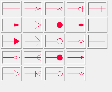
•Connection symbol – allows to select the graphical symbol that will be inserted in the place where lines connect. User can select one of the following symbols:


•Settings  –
setting up the scale (symbols’ size) and the Remove unnecessary connection points option, which
automatically searches for unnecessary connection points (e.g. remnant after
line removal) and removes them from the drawing.
–
setting up the scale (symbols’ size) and the Remove unnecessary connection points option, which
automatically searches for unnecessary connection points (e.g. remnant after
line removal) and removes them from the drawing.
|
•Ending of lines – allows user to select symbols that will be inserted in the beginning and ending of lines. |
|
•Settings –
setting up the scale (symbols’ size) and the Remove unnecessary connection points option, which
automatically searches for unnecessary symbols of line endings (e.g. remnant
after line removal) and removes them from the drawing.
Advanced Ortho – in this mode between the indicated points, two or three orthogonal segments are being drawn. This mode automates the process of connecting objects or lines while maintaining a right angle between the segments.
•2 segments – creates a line consisting of two segments.
•3 segments – creates a line consisting of three segments.
|
Notice Advanced ortho mode is available only in certain CAD programs. The first drawn segment can be vertical or horizontal depending on which way of the mouse movement is performed after selecting the first point (P1) of the drawn line. |
|
|
| |||
|
Advanced ortho 2 segments |
Advanced ortho 3 segments |
Draw with polyline – enables/disables drawing line segments as polyline.
End automatically – enables/disables automatic ending of lines when the drawn line is being connected to a different object in the drawing.
|
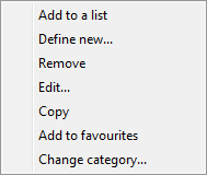
Pop-up menu – options menu for selected element/category which is available by clicking the right mouse button. Commands included in the menu are similar to the commands available on the dialog window toolbars. |
|
Procedures
1.
Run the Cable, cable trays - schematic  command.
2. (Optional) Select the line and click the OK button in order to allow the drawing of a single line without making changes in the settings.
3. In the newly opened dialog window pull-down the category that contains the desired line kind.
4.
Select the desired line and click the Add element to a
list button, or double click
on it in order to put it on the List of selected
lines.
5. (Optional) Repeat steps 2 and 3 in order to add more lines to the list.
6.
(Optional) Using the Copy selected rows , Remove selected
rows buttons add or remove the
selected line from the list.
7.
(Optional) Using the Move selected rows down/Move selected rows
up buttons change the order of
the lines on the list.
8. (Optional) Fill the information about type of line, enable/disable the Draw by type option.
9. (Optional) If there is more than one line on the List of selected lines specify the Spacing value.
10. Specify the way how you will draw the line and specify the Offset value if needed.
11. (Optional) If on the List of selected lines there is only one object then change the Drawing settings.
12. (Optional) If on the List of selected lines there is only one object you can set the connection and line endings options.
13. Enable/disable the End automatically option.
14. Click the OK button in order to start drawing a line (or several lines).
15. Specify the starting point and next segment points that you want to draw. In order to finish click the Enter key.
|
Notice Offset, additional angles, adding connection points, endings of lines, advanced ortho and end automatically options are available only when a single line is selected. |
Schematic lines are simple lines or polylines that's why it is also possible to draw lines with the CAD program standard commands such as Line or Polyline. However, it should be noted, that lines drawn in this way should be placed on appropriate layers. In order to match properties (e.g. layers), between the drawing objects, the Match properties (_Matchprop) command located in the CAD program can be used.
|
Hint The Schematic lines – ed). |
Drawing risers (vertical lines)
In schematic lines it is possible to present vertical lines segments using special symbols, such as risers.
Despite the fact that risers are being inserted using the Symbols - other) command, program treats them as schematic lines.
|
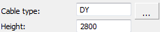
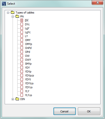
For risers user should specify the type of line and
height (length of vertical line segment). Line type can be selected from
the list that will be available after pressing the Browse
|
|
Data that is saved in the riser is included during the BOM creation when user uses the „Electrical – schematic cable trays” template (check page \* MERGEFORMAT 66).
 |
Installation view
 |
Scheme with risers view
Lines BOM view
Linetype scale for lines
|
Each line is being drawn with different line patterns, such as a dashed line (Dashed) used for the "Return" line. The line pattern density is set using the CAD command: Ltscale (_Ltscale). By default new drawings have got a linetype scale factor set as 1.00. If this factor number is too small or too big then line pattern may not be visible and all lines will be seen as drawn with a continuous line. |
Ltscale = 200
Ltscale = 50
|
In CADprofi program it's possible to design in units set as millimeters, centimeters or meters. For this reason, when drawing schemes the linetype scale should be always adapted to the edited scheme. For example, when drawing a scheme with the unit set as "millimeters" with symbol's size set as 200 then the linetype scale factor should be between the 50 and 200 range.
Defining new user lines
User can add his own type of lines to the program. In this way, program can be adapted to user's needs and can be used in a variety of projects in which it is necessary to draw schemes.
Procedures
1.
Run the Cable, cable trays - schematic command.
2.
Click the Define new button in order to add a new line to the
existing database. New element will be added to the *User* category. A new Edit
window will open, in which user will be able to specify all line parameters.
3.
(Optional) Select an existing line and click the Copy button to
create a new item. Selected line will be used as a template.
4. Change the new line settings in accordance with the Edit line data procedure.
*Favourites* category
It is also possible to create a folder that contains a list
of most frequently used installations by the user. This folder is created
automatically when a first element marked as favorite has been added to the program. In the
*favorite*category user can define any branch
structure, in which the individual elements will be located.
Edit line data
CADprofi allows to edit parameters (drawing features) of lines created by user. To do this, use the Edit option.
In CADprofi program pipe and ventilation lines can be drawn as schematic (with use of lines or polylines) or in 2D view. Therefore, when editing properties it is possible to specify different parameters for schematic lines as well as for lines in 2D view.
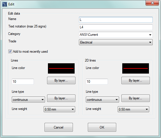
Edit line data dialog window
The Edit dialog window contains the following items:
Name – name of edited line.
Text notation – text marking for lines used as an ending of layer’s name in the extended layer structure.
Notice
It is recommended to use „unique values” of text notations in order to ensure proper recognition of lines by CADprofi.
Category – currently assigned category in CADprofi database.
Branch – currently assigned industry branch in CADprofi database.
Add to most recently used – this option adds the edited line into the default list of line types in the in the 2D Pipes – plan dialog window.
Lines or 2D lines – settings used for schematic lines or lines drawn in 2D:
•Line color – determines the line color. Color can be selected in several ways: by clicking on the button that contains the line preview, with the help of the by layer option or by entering CAD program color number.
•Line type – determines the line type (kind). Line type can be selected from the list of available line types or from the by layer option.
•Line weight – determines the line width. Line width can be chosen from the list available values in the program.
Notice
Only lines defined by user may be edited (it is not possible to change line parameters from the primary CADprofi database).
Procedures
1.
Run the Cable, cable trays - schematic command.
2.
(Optional) If the line that you would like to edit is located on the list of
selected lines, then select it and click the Remove
selected rows button in order
to remove it from the list.
3. On the List of available lines select the line that you would like to edit.
4.
Click the Edit .button A new dialog window will open, allowing
you to edit the line.
5. (Optional) Change the Name of edited line.
6. (Optional) Change the Text notation of edited line (not recommended if the edited line is already inserted in the drawing).
7. (Optional) Change Category of edited line.
8. (Optional) Change the Trade for selected line.
9. (Optional) Enable/disable the Add to most recently used option.
10. (Optional) Change parameters of schematical Lines.
11. (Optional) Change parameters of schematical 2D Lines.
12. Click the OK button to accept the changes.
|
Notice If you have changed the parameters for lines that have already been added to the drawing then in order to update their properties you will need to insert a new line (that has the new parameters) into the drawing. |
Installations from drawing
All lines and polylines that lie on appropriate layers are treated by CADprofi program as schematic lines. This includes layers with names similar to 2DX_PLS_xxx.
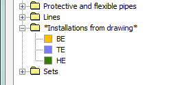
When several designers are working on the same project, then it is possible that one of these designers has used his own line kinds and then has forwarded the drawing to further edition. In this case, CADprofi application will automatically detect the presence of additional lines (installation kinds) and will display them in a new category called Installations from drawing. Name of the new lines that were identified from the drawing are being taken from their label (ending of the layer's name). If these lines' parameters will be edited in the dialog window, then they will be permanently saved in the program's database as user's lines.
|
|
It is possible to use Installations from drawing without the need of editing them, but in this case, on all BOMs the Installations from drawing lines will have their names listed as their layers' label. |
Lines’ layers
Each line kind is being drawn on separate layers. In order to easily manage layers in the top menu of CADprofi programs are located additional commands that allow to quickly hide or show all layers that belongs to central heating, sewage, water and other kinds of installations.
In the C:\ProgramData\Cadprofi\20XX.x\PlotStyle printing styles are located that suit the program's layers structure. Out of these files user can select monochrome printing (CADprofi Mono.ctb) and color printing (CADprofi Color.ctb).
*.ctb files should be copied to the appropriate folder of used CAD program.
For more information, please refer to the layers section (check page 35).


 button. Thanks to this, their
diameter data and length are being included in BOMs.
button. Thanks to this, their
diameter data and length are being included in BOMs.