Fittings and air condition ducts with a rectangular cross-section that are prepared from steel are usually connected with the use of flanges. In CADprofi such elements are simplified (without flanges) therefore user should specify in the project the type or the technology used in the air condition lines. An appropriate annotation should be included in the descriptive section. If necessary, it is possible to insert flanges into the drawing with the use of appropriate CADprofi command. Designer can also decide whether the flanges inserted in the drawing should be included in the specification.
The simplified drawings allow to use most lines and fittings from the CADprofi program in any installation projects that use different technologies, materials and connection methods (e.g. metal and artificial/plastic lines installations etc.).
During the specification creation it is possible to add the area of lines and fittings. The area is being calculated on the basis of the PN-EN 14239 standard.
In specifications it is possible to add dimensions or types (markings) of fittings or lines. Fitting type is available only in the case of using elements that are chosen from manufacturers’ databases. In another case type is not specified and in the specifications only the main dimensions are included. These dimensions are appropriate with markings that are included in the catalog of 2D fitting drawings. We propose to print and add the catalog of 2D fittings to the specification. The catalog of 2D fittings can be found in the Fittings.pdf folder that is located in the file_gb folder, which can be found in the CADprofi installation folder.
|
Hint Add the „Fittings.pdf” printing to the fitting’s specification. |
Cable trays, cable ladders, protective tubes and other elements are available in the Electrical module. Some fittings that are in the 2D fittings catalog are not used in electrical installations and therefore they are not available in the Electrical module.
Flexible cables with a circular cross-section (FLEX) or flexible protective tubes from the Electrical module are drawn with the help of straight sections and fittings. Still fittings are being treated as lines/cables therefore in specifications all flexible elements are being shown as flexible lines with specified length.
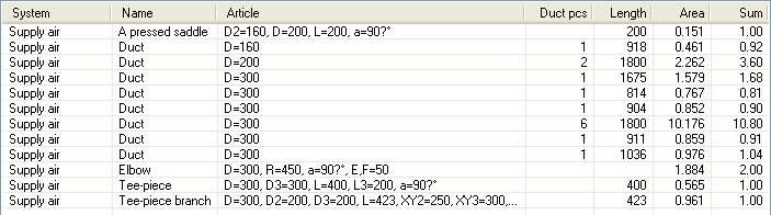
In order to include length and the amount of each line/duct/cable tray sections in the specification user should add both Length and Ducts pcs (number of pieces) columns.
In order to add only the total length of line/duct/cable tray with the same cross-section in the specification, user shouldn't include the No., Length and Ducts pcs columns.
An example of a specification of air conditioning installation elements:
|
This column includes the number of lines/ducts sections with the same length. E.g. 6 sections with an 1800 mm length. |
|
In the Length column the element length is specified in mm. E.g. sections with a 1800 mm length |
|
The Area column contains the element area in m2 or the total area of all elements that were included in the specification. |
|
The Sum column contains the total length of lines / trays / ducts in meters. The Sum column is shown only if user has enabled the Summing data option during the specification creation. |
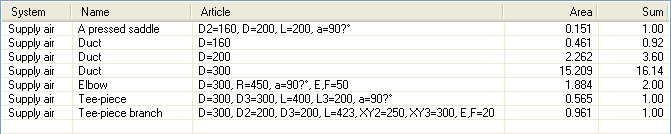
Fittings
|
Fittings types or dimensions are shown in the Article column. All dimensions are the same as those that are used in the drawings from the catalog of 2D fittings. |
|
In the air condition installations, it is possible to add the Area column that contains area (in m2) of elements that are counted accordingly to the PN-EN 14239 standard. |
|
For fittings the Sum column contains the total amount of fittings from each type. |
In the above example there are two 90º elbows in the
specification with
an ø300 diameter and R=450 (1,5D) radius.