Attributes and
descriptions
Attributes and
descriptionsDuring the symbols and objects insertion, CADprofi program is adding various descriptions and technical parameters to them. This data is stored as attributes. The Attributes and descriptions command allows to edit the attributes, as well as to add descriptions (as a simple text) into the drawing. All data that is used in the attributes can be later used during the BOM creation.
After user chooses the command he should indicate an object, whose parameters he would like to edit. This command gives the possibility to edit many objects thank to the Multiple function ("M" key). As an effect it will be possible to edit parameters of all indicated blocks.
After indicating the objects a new dialog window that contains all attributes will appear.
If user has selected several object it's possible that a ***Varies*** value may appear in some data. It means that objects have got different values of a specific parameter. Editing this parameter will also edit it in all of the selected blocks. If this parameter won't be edited then the value won't change in any of the selected blocks.
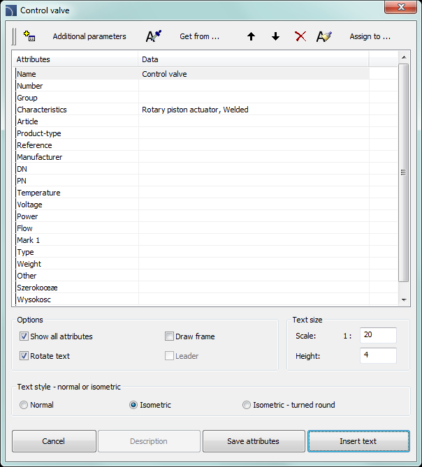
Attributes and descriptions dialog window
The Attributes and descriptions dialog window contains the following items:
List of parameters – list that contains all attributes and their values from selected blocks.
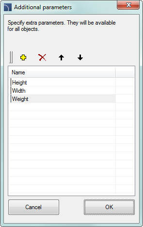
Additional parameters– this button opens a new window of additional parameters, that are defined by the user.
|
•Add •Delete •Move up •Move down |
|
Recover parameters  – allows to recover additional parameters
from the unassigned values that are contained in the object. These parameters
will receive the default name, that's why it is recommended to change it.
– allows to recover additional parameters
from the unassigned values that are contained in the object. These parameters
will receive the default name, that's why it is recommended to change it.
|
Notice It is possible to only edit attributes of objects that were inserted to the drawing with CADprofi commands. |
Get from… – allows user to get the selected attributes from the object indicated in the drawing. If the specified object does not have any parameters or their value is empty the operation will not be performed.
Assign to… – allows to assign selected attributes to objects indicated in the drawing. This is a convenient option that's used to agree objects attributes.
Move selected rows up
 /down
/down  – moves the selected attribute up/down one
position on the list. This option is needed when user wants to select attributes
and insert them in a specific order as a text into the drawing.
– moves the selected attribute up/down one
position on the list. This option is needed when user wants to select attributes
and insert them in a specific order as a text into the drawing.
Delete contents of selected
attributes  – clears the data
from selected attributes.
– clears the data
from selected attributes.
Show all attributes – switches between two views: show all available attributes and show only attributes that are filled with data.
Rotate text – enable/disable the ability to rotate the text when inserting it into the drawing.
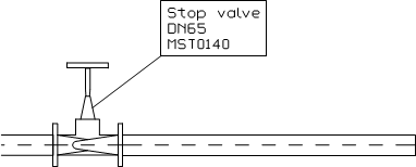
Draw frame – enable/disable the frame for the text, that will be inserted into the drawing.
Leader – allows to draw a line between the object and the inserted text.
Text size – options that specify the size of inserted text.
•Height – specifies the block text height in millimeters.
•Scale – allows to specify the scale in which the drawing will be printed.
Text style: normal or isometric – allows to specify the text style in both normal and isometrical views.
Description – opens window with an optional object description. This function is used only in certain objects from the manufacturers databases.
Save attributes – closes the dialog window and saves all the changes in selected blocks.
Insert text – saves all
the changes made in the selected blocks, and allows to insert to the drawing the
value of selected attributes as a plain text. In order to insert the text, user
should indicate a point that specifies the first line of text. Depending on the
rotation option, it may be necessary to indicate a second point that specifies
the text rotation angle. Instead of indicating a second point it's possible to
indicate the angle size (e.g. "0" or "90"). In this case, the text will be
inserted horizontally.
The style of the inserted text depends on the current
CAD program style.
 |
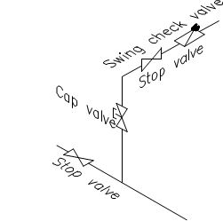
Description in axonometric drawings
The Insert text command allows to insert texts in axometric drawings. In order to insert text in isometry or dimetry user should select the Text style – isometric option.
|
When inserting text in isometry CADprofi will activate the isometric mode for the graphic cursor, thanks to which it will be easier to determine the position and text insertion angle along the desired axis. Isometric cursor is automatically set only when the isometric angle is set to 30°. When inserting text in dimetry it is convenient to enter the text angle in the command line. The angle should be set in accordance with the axonometrical angle that is set in CADprofi Options (page 31) dialog window. |
|
 –
adds a new parameter to the list. This parameter will be visible in all
program objects as well as in the
–
adds a new parameter to the list. This parameter will be visible in all
program objects as well as in the