Both Symbols and Ventilation - Symbols commands allow to insert various symbols from the available library.
When inserting symbols into a line, application will automatically break the line in the insertion point, while maintaining the rules of creating schematic drawings.
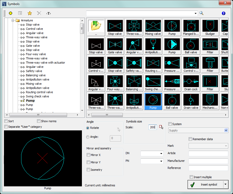
Symbols dialog window
The Symbols dialog window contains the following elements:
Tools menu:
 Define
new - allows to add a new element to the database. Read more about
it in the Defining user
blocks.
Define
new - allows to add a new element to the database. Read more about
it in the Defining user
blocks.
 Edit
- allows to Editing user block parameters.
Edit
- allows to Editing user block parameters.
 Add to favourites
- copies symbol to the *Favourites* category.
Add to favourites
- copies symbol to the *Favourites* category.
 Delete - deletes the selected symbols from the *Favourites* category.
|
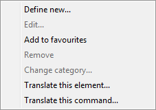
Pop-up menu- options menu for the selected symbol, which is available after right clicking on the mouse button on the selected symbol. Commands in this menu are similar to the tools menu. |
|
Category tree - a set of all categories and symbols in the library, shown as a pull-down tree. User can customize the display order by using the following options:
•Sort - alphabetical order of categories placement and their content.
•Norms- enables/disables displaying symbols according to norms.
Thumbnail view - displays the content of currently selected category as thumbnails.
Preview - displays the preview of the currently selected symbol. Right-clicking on the preview window will zoom the view.
Angle/Rotation
- possibility to specify a fixed angle when inserting symbols or
enabling the rotation option, in which symbol's angle is defined by rotation
during insertion.
During insertion of symbols into lines, the insertion
angle depends on the line angle (the angle specified in the dialog window is
being ignored).
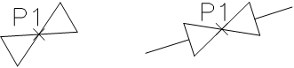
When inserting symbols into lines it is possible to use the
Rotation option in
order to dynamically specify symbol rotation relatively with the line. This
option is very convenient when inserting symbols of pumps, valves etc.
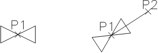
0° angle Rotation
30° angle Inserting into a line
Scale - specifies the size of inserted symbols. It is possible to enter the scale value or to indicate a symbol on the drawing whose scale user would like to use.
System - if in the program options, the extended layer name structure is enabled then symbols will be inserted on layers depending on the kind of installation (system). In case of inserting symbols into an existing line then the System option is being ignored and the symbol layers depends on the line kind.
Mirror and isometry:
•Mirror X, Y- enabling this option will create an X or Y mirror image for the specified object.
•Isometry - enabling this option will convert the symbol, so it will possible to use it in isometrical schemes.
This option may not be available for some symbols.
Object data - this option allows to specify symbols technical or identification parameters. For each symbol, different parameters can be given such as: Article, Manufacturer, Reference (Catalog number), DN, PN and others. In order to fill the parameters, enter any text or choose a value from the available list.
Remember data - this option allows to save the user entered parameters. This option should be enabled when user inserts symbols with similar characteristics.
Insert multiple - enables/disables the possibility of inserting multiple symbols to the drawing. The insertion process requires from the user to press the Enter or Esc key when he finished inserting multiple symbols.
6 Procedures
1.
Run the Symbols  or Ventilation - Symbols
  command.
2. In the dialog window choose the appropriate category.
3. Select the symbols that you would like to insert. In the bottom-left corner of the dialog window a preview of the selected symbol will be displayed.
4. Specify the insertion parameters: System, Rotation, Scale.
5. (Optional) In accordance with your preferences fill out the value of following parameters: Article, Manufacturer, Reference, DN, PN.
6. Click the Insert symbol button in order to specify the symbol insertion point.
7.
(Optional) With the use of the  button pull-down the insertion list and
choose In extension to specify the insertion point
in accordance to other objects.
button pull-down the insertion list and
choose In extension to specify the insertion point
in accordance to other objects.
8.
(Optional) With the use of the button pull-down the insertion list and
choose Into point to insert the symbol in a
specific point.
9.
(Optional) With the use of the button pull-down the insertion list and
choose Into many lines to insert symbols
simultaneously into many lines.
10. Click on a point in the line to insert the symbol.
11. (Optional) Click on any point in the drawing, to insert the symbol without inserting it on a line.
12. (Optional) Specify the inserted symbol angle - this option is available only if the Rotation option in the library dialog window has been enabled.
13. After closing the dialog box, insert the symbol into the drawing.
 Symbols