
Inserting an IEC multipole symbol

Inserting a NFPA multipole symbol
The Symbols - IEC, NFPA command allows to insert controlgear, switchgear, complex apparatus, measuring instruments and many additional symbols and elements that are used in electrical installations scheme. In the library there are symbols from both IEC and NFPA standards available.
During the symbol insertion it is possible to automatically enumerate objects and determinate connections as well as add information about additional technical parameters.
Inserting symbols into lines will automatically interrupt them in the insertion point, while maintaining the principles of creating schematic drawings. This rule also applies to multipole apparatus, but in this case, user has to match the line to the type and scale of multipolar symbols.
|
Inserting an IEC multipole symbol |
Inserting a NFPA multipole symbol |
For IEC symbols the offset between each lines is 5 (or a multiple of 5), whereas for NFPA symbols it is 3/8” (0.375).
|
Hint Templates for potential lines and line circuits that are available in the Frames and tables) command have been prepared in such a way allow the correct insertion of multipolar symbols, on condition that they have the appropriate scale. |
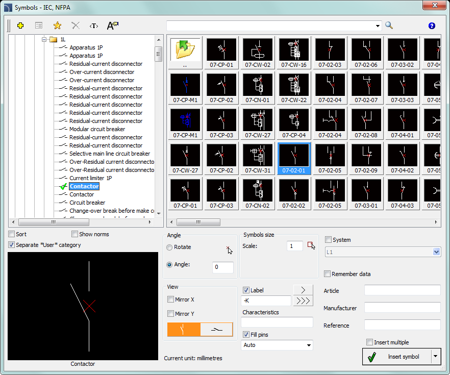
Symbols – IEC, NFPA dialog window
The Symbols - IEC, NFPA dialog window contains the following items:
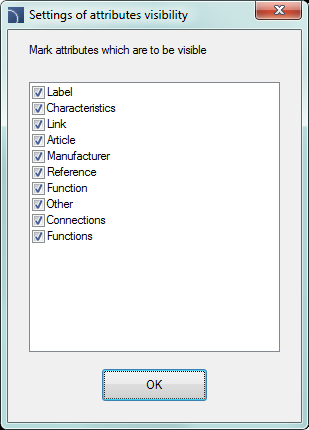
Attributes visibility – this option is used to specify which attributes should be visible when inserting symbols.
|
After clicking the button, a dialog window will open with a list of available attributes. Editing the attributes can be performed after the symbol insertion by using theAttributes and descriptions) command or by using the Ddedit (_Ddedit) command in the CAD program. |
|
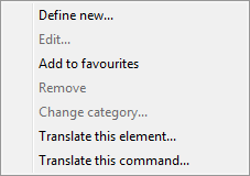
Tools menu:
•Define new  –
allows to add a new element to the database. Read more about it in the Defining user
blocks).
–
allows to add a new element to the database. Read more about it in the Defining user
blocks).
•Edit  – allows
to Editing user block
parameters).
– allows
to Editing user block
parameters).
•Add to favourites  – copies symbol to the *Favourites* (check page 303).
•Delete  –
deletes the selected symbols from the *Favourites*
category.
–
deletes the selected symbols from the *Favourites*
category.
|
Pop-up menu– options menu for the selected symbol, which is available after right clicking on the mouse button on the selected symbol. Commands in this menu are similar to the tools menu. |
|
Categories tree – a set of all categories and symbols in the library, shown as a pull-down tree. User can customize the display order by using the following options:
•Sort – alphabetical order of categories placement and their content.
•Show norms– enables/disables displaying symbols according to norms.
Thumbnail view – displays the content of currently selected category as thumbnails.
Preview – displays the preview of the currently selected symbol. Right-clicking on the preview window will zoom the view.
Mirror X, Y – enabling this option will create an X or Y mirror image for the specified object.
Go to the vertical / horizontal
symbol ( ) – toggles between vertical
and horizontal views.
) – toggles between vertical
and horizontal views.
Angle/Rotation – possibility to specify a fixed angle when inserting symbols or enabling the rotation option, in which symbol's angle is defined by rotation during insertion During insertion of symbols into lines, the insertion angle depends on the line angle (the angle specified in the dialog window is being ignored). When inserting symbols into lines it is possible to use the Rotation option in order to dynamically specify symbol rotation relatively with the line.
|
| ||||
|
0° angle |
Rotation | |||
|
| ||||
|
30° angle |
Inserting into a line without rotation | |||
Scale – specifies the size of inserted symbols. It is possible to enter the scale value or to indicate a symbol on the drawing whose scale user would like to use.
System – if in the program options, the extended layer name structure (check page. 32) is enabled then symbols will be inserted on layers depending on the kind of installation (system). In case of inserting symbols into an existing line then the System option is being ignored and the symbol layers depends on the line kind.
Object data – this option allows to specify symbols technical or identification parameters. For each symbol, different parameters can be given such as: Article, Manufacturer, and others. Available options and parameters depend on the symbol type.
Remember data– this option allows to save the user entered parameters. This option should be enabled when user inserts symbols with similar characteristics.
Label – gives the
possibility to add subsequent labels to inserted symbols. Label field is
automatically filled with default marking and the first free number. Thanks to
the available buttons, user can choose between the first free number  and a subsequent number
  . This field can be also filled with any
value.
. This field can be also filled with any
value.
Fill pins – numbering of connections in the inserted symbol. Numbering type can be chosen from the drop-down list:
•Auto – numbering of all connections, starting from number 1.
•1/2… or a/b… – allows to possibility to manually number connections. This option allows user to enter values himself for subsequent connections, separating them with the”/” sign.
|
| |
|
Automatic numbering |
Numbering: A1/A2/1/2/3/4/5/6/13/14 |
|
Hint Entering the "//" characters in the numbering field will allow to bypass the next connection. |
Insert multiple– enables/disables the possibility of inserting multiple symbols to the drawing. The insertion process requires from the user to press the Enter or Esc key when he finished inserting multiple symbols.
Some apparatus symbols are multivariant symbols, thanks to which user can insert to the project apparatus that contain any configuration of contacts, triggers etc. Such symbols substitute many "traditional" symbols in the library. In this way it's easier to use the program, and at the same time it gives user more opportunities to define custom elements.
Multivariant symbols can be edited with the Edit symbols command.
trigger
selection contact
selection mechanism
selection


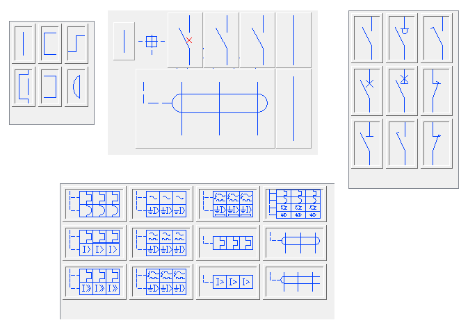

Example of a multivariant symbol
Procedures
1.
Run the Symbols - IEC, NFPA  command.
2. In the Symbols - IEC, NFPA dialog window choose the appropriate symbol. In the bottom-left corner of the dialog window a preview of the selected symbol will be displayed.
3. Specify the insertion parameters: System, Rotation, Scale.
4. Enable/disable the use of a Label, specify the label element, e.g. –F8.
5. Enable/disable the fill pins option, specify the type.
6. (Optional) Fill out the value of following parameters: Article, Manufacturer, Reference.
7. Click the Insert symbol button in order to specify the symbol insertion point.
8.
(Optional) With the use of the  button
pull-down the insertion list and choose In
extension to specify the insertion point in accordance to other
objects.
button
pull-down the insertion list and choose In
extension to specify the insertion point in accordance to other
objects.
9.
(Optional) With the use of the button
pull-down the insertion list and choose Into point
to insert the symbol in a specific point.
10.
(Optional) With the use of the button
pull-down the insertion list and choose Into many
lines to insert symbols simultaneously into many lines.
11. Click on a point in the line to insert the symbol.
12. (Optional) Click on any point in the drawing, to insert the symbol without inserting it on a line.
13. (Optional) Specify the inserted symbol angle - this option is available only if the Rotation option in the library dialog window has been enabled.


 Schemes: working with
symbols
Schemes: working with
symbols