In order to create a specification or a legend with the help of the specification wizard user should press the Draw button. Two modes are available: Legend and Specification.
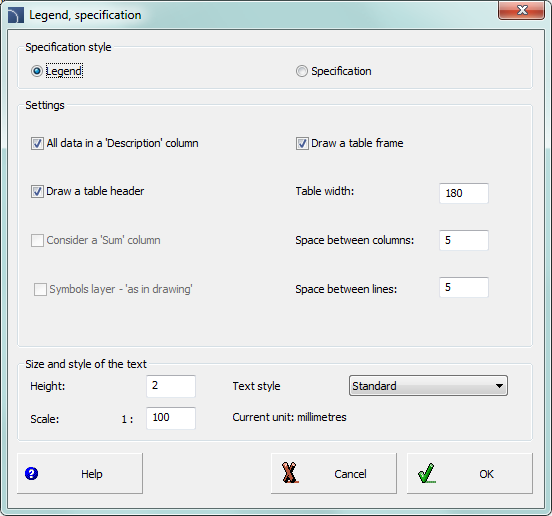
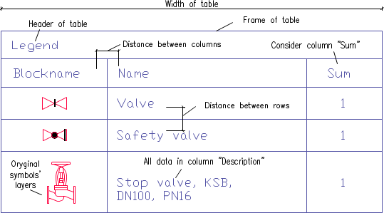
The Legend mode is used to create any defined legends or specification tables. In this mode it is possible to determine the overall table width, the spacing between columns and rows and the text style. The legend may contain a header with a specification title and the titles of each column.
The Description column is particularly important. After enabling the option: All data in the 'Description' column, the legend will be created in which all data that will be acquired from the drawing will be consolidated into one description column.
When disabling the above option, it is possible to create tables that contain many columns.
Legends that contain symbols and objects views are created only if the Block column has been selected in the specification wizard. In this case symbols that are in the legend can be placed on layers accordingly to symbols layers in the drawing. Thanks to this, symbols that are in the legend have got saved colours and characteristics of the original objects from the drawing.
|
Notice |
Legends columns width is determined in proportion to the column width that is set in the main data window. After setting the mouse cursor between the columns, the cursor changes into a double-headed arrow that allows to change the width.
Legend, specification dialog window
6 Procedures
1.
Run the Bill of materials  command.
2. Choose one of available templates, in order to specify the BOM type.
3. (Optional) Add or delete positions in the Printed columns chart.
4. (Optional) Choose the printing option for specification.
5. Click the Next button.
6. Select objects from the drawing that you would like to include in the specification. Confirm by pressing the right mouse button or the Enter key.
7. (Optional) Specify the settings in the data window.
8. Click the Draw button.
9. In the newly opened Legends, specifications window choose the Legend option.
10. (Optional) Specify the specification table settings.
11. (Optional) Specify the text size and style.
12. Click the OK button.
13. (Optional) Select Yes/No in the newly opened dialog window in order to delete/save the existing legend.
14. Specify the legend insertion point.
|
Notice There is a set of names of each parameter in the program such as: "Name", "Type", "DN", "PN" etc. In certain tables it is necessary to use other names, e.g. the parameter "Type" in some tables is the equivalent to the "Symbol" or 'Marking" parameter. |
The Specification mode is used to fill template specification drawing tables. These specifications are prepared on the basis of appropriate standards. Because of that the specifications tables have got a precisely defined structure (column width, appropriate text size and style etc.). When inserting a specification table into the drawing, user should make sure that he has chosen the right columns with data in the specification wizard, that belong to the appropriate table type. Otherwise, the tables won't be properly filled. The All data in the ‘Name’ or ‘Description’ box allows to consolidate the data in the column that contains a name.

Legend, specification dialog window
6 Procedures
1.
Run the Bill of materials command.
2. Choose one of available templates, in order to specify the BOM type.
3. (Optional) Add or delete positions in the Printed columns chart.
4. (Optional) Choose the printing option for specification.
5. Click the Next button.
6. Select objects from the drawing that you would like to include in the specification. Confirm by pressing the right mouse button or the Enter key.
7. (Optional) Specify the settings in the data window.
8. Click the Draw button.
9. In the newly opened Legends, specifications window choose the Specification option.
10. (Optional) In the Settings chart select the Specification type.
11. (Optional) Enable/disable the All data in the ‘Name’ or ‘Description’ box option.
12. (Optional) Change the text size and style.
13. Click the OK button.
14. (Optional) Select Yes/No in the newly opened dialog window in order to delete/save the existing specification.
15. Specify the specification insertion point.
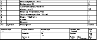
An example table contains columns with No., Symbol (type), Description, and Sum. In this case in the specification wizard user should choose the Type and Name columns. Sum column is being filled only if the Summing data option is enabled. No. column is filled only if the Ordinal number on print option is enabled.
 Creating
graphical
legends
Creating
graphical
legends