Shaft
generator  command allows user to automatically
generate multi-stage shafts from user-selected components. At any stage of the
project, user can make corrections, such as adding more shaft stages and
changing dimensions. It is also possible to move and copy shaft stages using the
drag-and-drop function.
command allows user to automatically
generate multi-stage shafts from user-selected components. At any stage of the
project, user can make corrections, such as adding more shaft stages and
changing dimensions. It is also possible to move and copy shaft stages using the
drag-and-drop function.
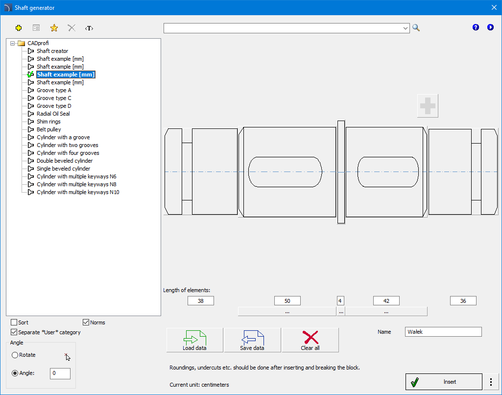
"Shaft Generator"
dialog box
Shaft generator dialog box contains:
Tools menu:
 Define
new - ads a new element to the database. The method of extending
the database is described in the Defining User Blocks chapter.
Define
new - ads a new element to the database. The method of extending
the database is described in the Defining User Blocks chapter.
 Edit
- allows user to edit an item from the "User" directory.
Edit
- allows user to edit an item from the "User" directory.
 Add to
favorites - adds an item to the user's *Favourites*.
Add to
favorites - adds an item to the user's *Favourites*.
 Delete - deletes the selected object from the *User*
category.
Delete - deletes the selected object from the *User*
category.
 Translate
command - opens a glossary of terms used in the command dialog and
allows user to add his own user translations.
Translate
command - opens a glossary of terms used in the command dialog and
allows user to add his own user translations.
 Help
- contains a link to the online support file.
Help
- contains a link to the online support file.
 Video -
contains a link to an instructional video.
Video -
contains a link to an instructional video.
This
command also allows user to search for items in the entire database.
Dialog box also contains:
Category Tree - a
collection of all categories and items contained in the library, presented in a
hierarchical form. It is possible to adjust the order in which items are
displayed on the list by using the following options:
• Sort - arrange the category and its contents in
alphabetical order.
Shaft Generator - an
area where user can create and edit a shaft using a graphical preview.
 Add
segment - button for adding a shaft segment.
Add
segment - button for adding a shaft segment.
Element length - field that allows user to enter
the length of individual shaft segments.
 Add/Remove segment - allows user to remove
or add a segment of the shaft.
Add/Remove segment - allows user to remove
or add a segment of the shaft.
 Load data - allows user to load a previously
saved file with the shaft model.
Load data - allows user to load a previously
saved file with the shaft model.
 Save
data - allows user to save the current shaft model to a file on
the disk.
Save
data - allows user to save the current shaft model to a file on
the disk.
 Clear all - allows user to clear the entire shaft
model in the generator window.
Clear all - allows user to clear the entire shaft
model in the generator window.
Angle/Rotation - allows user to insert the
created block at a given angle, rotation allows you to insert an object in the
drawing at any angle.
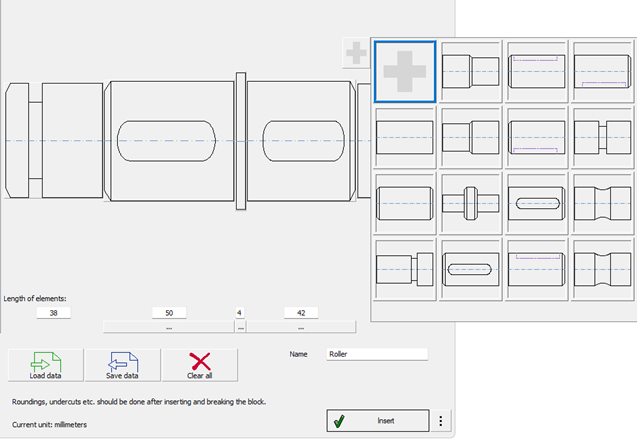
“Shaft generator” dialog box with component
selection window.
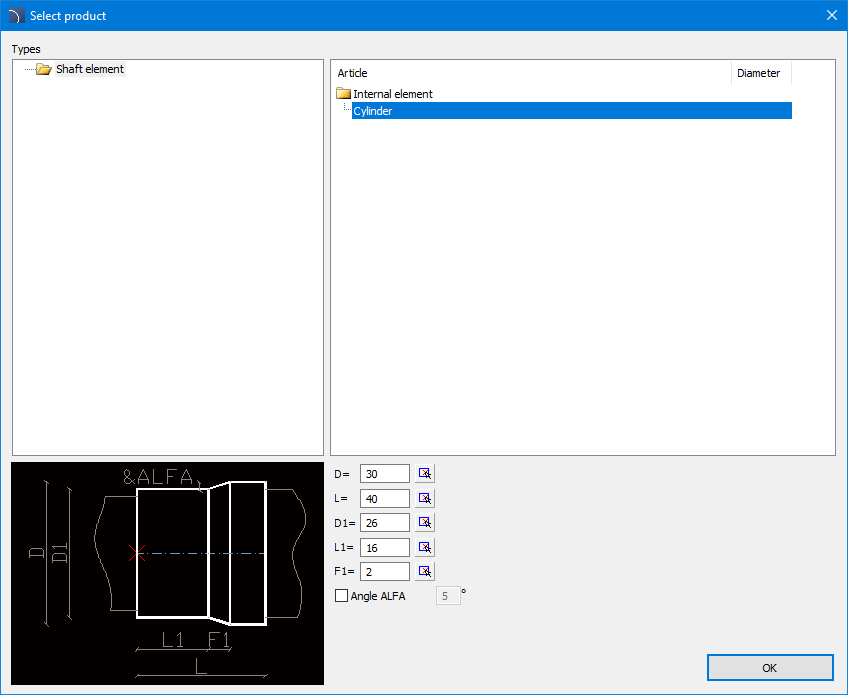
Component Edit dialog window
6
Procedures
Generation of shafts
1.
Run Shaft generator
command.
3. In the dialog window, create a
model of the shaft by adding its segments and adjusting their dimensions. A
preview of the currently created object will be displayed.
3. (Optional) Use the sample shaft
design or load a file with a ready model. Edit it.
4. Press the Insert button.
5. Select the object's insertion
point in the drawing.
 Shaft
Generator
Shaft
Generator