The Flowcharts and diagrams command contains elements that are used to draw a variety of functional diagrams, network infrastructure, technological process models and block diagrams.
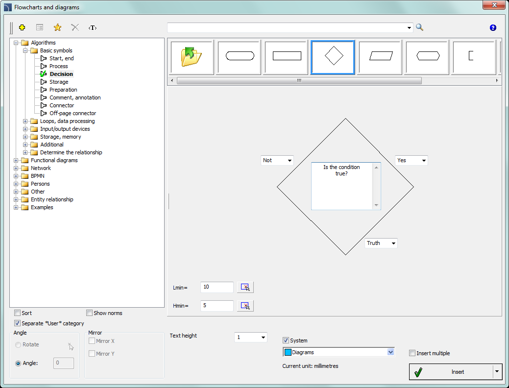
Flowcharts and diagrams dialog window
Many block diagrams elements has got edit fields, in which it is possible to enter a variety of texts. Program automatically adjusts the size of elements that are inserted into the drawing depending on the text length. If user needs to edit the text, then he can use the Edit symbols command, thanks to which after making the edition the block size will be updated. It is also possible to determine the minimum size of the block, so even when adding small amount of texts, the size of individual elements will be similar.
All ways of working with symbols are fully explained in the individual modules chapters.
Examples of block diagrams and flowcharts:
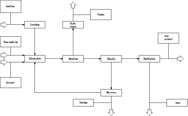
This drawing shows an example block diagram of an industrial installation.
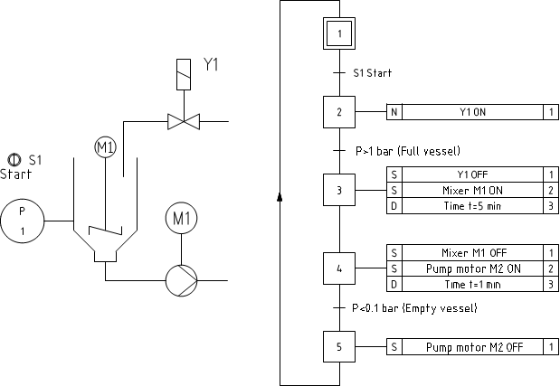
Functional diagrams, drawn according to the EN 60848 standard.
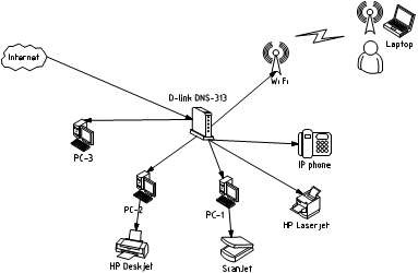
Creating computer network and infrastructure diagrams.
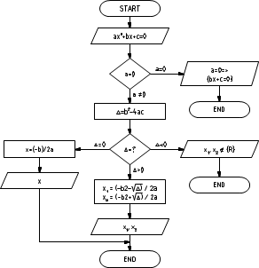
An example of an algorithm
Program can draw BPMN diagrams. Business Process Modeling Notation is a graphical way of showing business processes.
BPMN describes three basic types of processes:
•internal process
•public process
•cooperation process
In CADprofi program the following BPMN graphical elements categories are available:
•active elements
•connections
•location of the process
•graphical elements used to add additional information (data, annotations and groups)
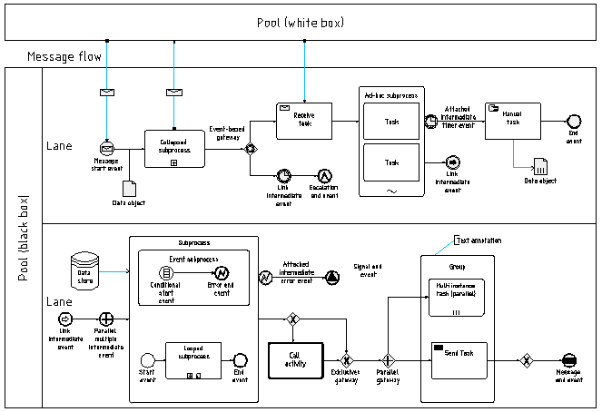
An example of a BPMN diagram