The Elko-Bis
component library allows you to designing any lightning protection system.
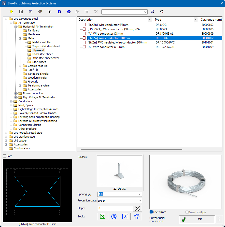
This library is available in the Products library command.

The main division of Elko-Bis products is based on the level of protection provided by the devices. Each of the four LPS class folders contains components made of steel, copper, and aluminum. Each of these subcategories contains the blocks necessary to create a complete lightning protection system drawing.
Lightning protection wires and linear earth electrodes
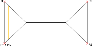
All lightning conductors, lightning protection wires, and earth electrodes laid in trenches are drawn using lines placed on strictly defined layers. These layers are created automatically depending on the selected element.
Example layer name: 2DE_PLS_Eb-$Cu$d7$59.1CU $S30p where:
2DE_PLS_Eb - standard CADprofi prefix,
$Cu - material of the wire,
$d7 - diameter of the wire cross-section,
$59.1CU - designation of the wire fastening,
$S30p - slope value expressed as a percentage.
The wire material, its diameter, fastening type, and slope are specified in the library dialog box.
This solution allows you to draw conductors using the standard CAD Line command and then match their properties to the appropriate layer using the _Matchprop command.

Example of drawing deceptions with the “right” option and a 50 offset
Down conductors and linear grounding conductors running along the wall
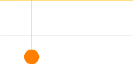
The application also allows you to insert vertical grounding conductors and down conductors. These objects are visible in the drawing as vertical symbols, and all information about their length and fastening will be saved as block attributes.

Connectors and other components
In addition to wires, the application also allows you to insert any connections, control connectors, pin grounding terminals, and enclosures. All components are placed in the appropriate categories for the given material and protection class.
The process of inserting symbols is the same for all elements of this type.
Control connectors
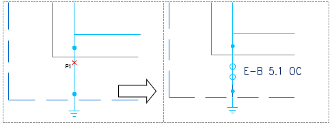
The Elko-Bis library allows you to insert control connectors. A connector block inserted into a cable does not cut it. To remove the unnecessary fragment, use the Trim command in the CAD program.

Masts and spires
The masts and spires included in the library have a protection range defined by the manufacturer and visible in the drawing. It depends on the selected LPS class. These objects can be inserted both in the view (used in projections) and in the side view used in elevation drawings. The process of placing these objects in the drawing is analogous to placing connection blocks.